This section will provide helpful modeling tips and best practices for modeling slabs in RISAFloor ES.
If you have a support line that is very long, you can breakup the support line into two segments in order to get only half the support line in the Detail Report. The only limitation to breaking up a support line is that at the intersection of the two support lines, the top reinforcement will not be forced to be uniform spacing. Otherwise the design will be the same no matter how many spans the support line has.
The mesh size can contribute to slow run-time. If you increase the mesh size, usually the model will run faster. The mesh size defined in the Model Settings - Solution tab defines the maximum mesh size of finite elements created for the slab floor. There are minimum numbers of plates required between control points so even if you set the mesh size larger than the default the program will make sure there are enough plates. To can review the mesh size, go to the Model Display Options - Slabs tab and check the Outline Plates box.
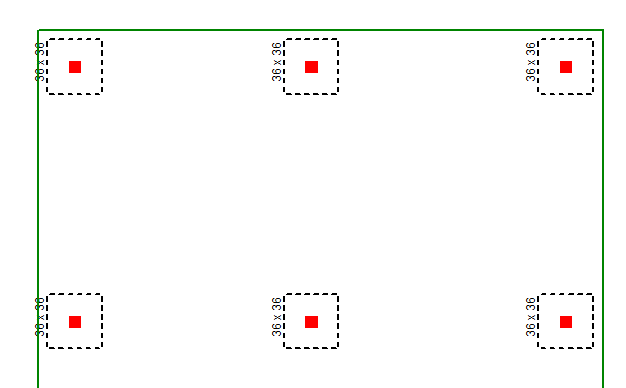
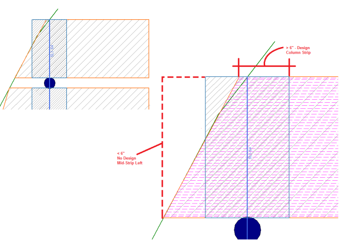
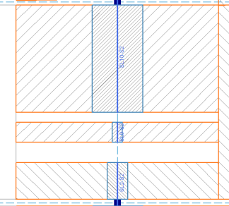
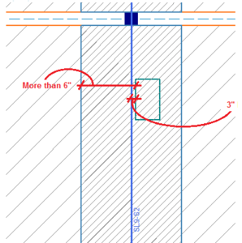
In order to get reinforcement design and analysis information, there must be a cut of at least 6" at the start and end of the Design Strip span. Below demonstrates the different ways that you might not get design for all or part of the strip.
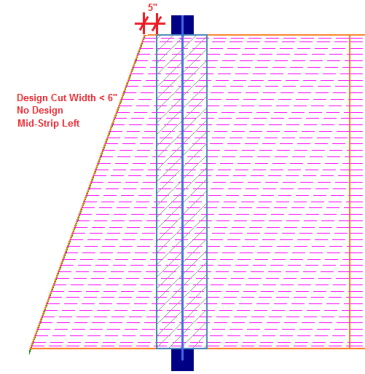
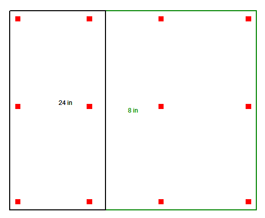
Example 1: The Mid-Strip Left has the first cut of 5" which is less than 5". The Column Strip and Mid-Strip Right will have design.
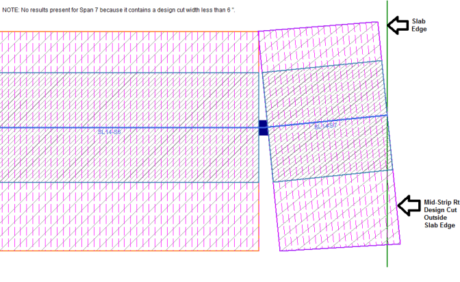
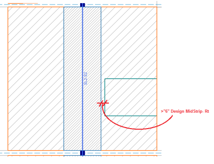
Example 2: The first Mid Strip Rt Design Cut is outside the Slab edge.
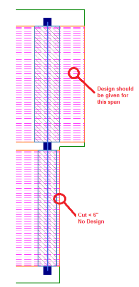
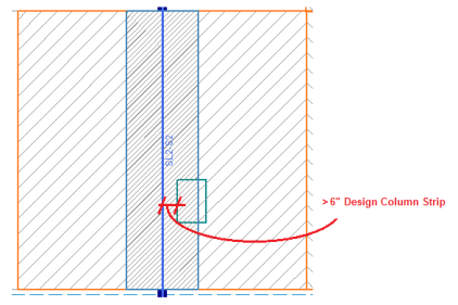
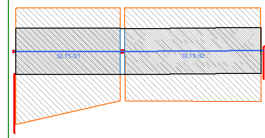
Example 3: Each span is determined individually within a support line.
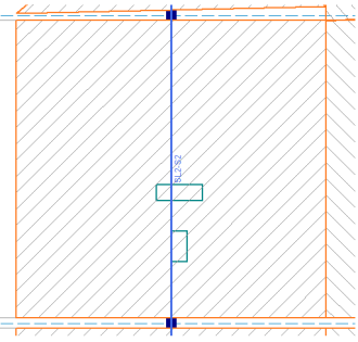
Example 4: The slab edge can interrupt the design strip and that can cause no design for a portion of the strip. In this example, the Column Strip still has at least 6" and the Support Line is not interrupted by the slab edge so it will get a design.
Example 5: Openings can cause the Design cuts to be less than 6".
Example 6: Openings can cross over support lines. The openings will split up the support lines into separate segments around the openings.
Example 7: This example shows an opening that doesn't cross the support line and it's fully contained within the column strip. It will not break up the support line as shown above unless it crosses the support line. There will be design for this column strip example as long as the cuts are at lease 6".
There are three methods to vary the slab thickness; Drop Panels, Shear Caps and Thickened Slab Region.
The Drop Panel will thicken the Column Strip only. This can be helpful when the forces are concentrated in the column strip and the added depth of the slab will reduce the reinforcement. The drop panel will be indicated in black outline around the Column Strip. For more information on adding a Drop Panel, see Drop Panels section.
Thickened Slab also allows you to change the thickness of the slab using a Polygon or Rectangular shape any location on the slab. This tool allows you to draw any free-formed shape so it can be used for entire section of the floorplan (example shown below) or just a smaller section. For more information on adding a Thickened Slab region, see Drop Panels section.
Shear Caps allow you to thickened the slab around a column. In practice this is refered to a shear cap, drop cap, or capital. Shear Caps are used when the punching shear calculations indicate that the slab thickness isn't adequate. The shear cap will thicken the slab in the area around the column top. For further information on Shear Caps, see the Punching Shear Considerations section.